


English
- English

CONTACT US
If you have any queries, get in touch today! Don't hesitate. We try to take the extra step for our customer satisfaction.
Our News
Carbon Conversions offers recycling solutions to companies that need to dispose of excess carbon fiber from decommisioned parts.
The development partners overcame cultural and geographical challenges,
2025-12-05 08:38:12
Click:
“
The
development partners overcame cultural and geographical challenges,ensuring
”
The development partners overcame cultural and geographical challenges,
ensuring the successful completion of the curing process for this large composite structure for the Boeing Dreamliner.
On May 26, 2005, Boeing awarded the production contract for the full composite central wing of its 787 Dreamliner to Fuji Heavy Industries (FHI, Nagoya, Japan). This critical structural component, which connects the wing to the fuselage, measures 17.4 feet in length (front-to-back), 19 feet in width, and 4 feet in thickness (5.3 meters × 5.8 meters × 1.2 meters). Even before the contract was signed, this long-term development partner of Boeing (and also a Subaru automobile manufacturer) had already begun
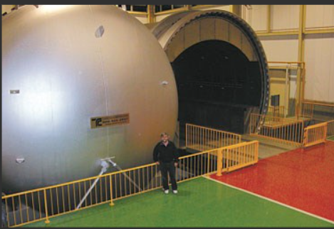
A facility with an area of 1 million square feet (over 92,900 square meters) was constructed for the production of this structure. The largest equipment in the new factory is a hot press tank approximately 23 feet long and 23 feet in diameter (7 meters x 7 meters), used for curing the central wing. The manufacturing of this hot press tank began nearly a year ago and was initiated by the equipment manufacturer Taricco Corp (Long Beach) on the other side of the world.
This project was extraordinary for Taricco Corp. Not only because this hot press tank is one of the largest equipment built by the company in its history, but also because it was the first time the company did not assume full project responsibility. Taricco Corp. was only responsible for the design and material supply of the hot press tank and was only allowed to serve as a technical supervisor during the construction and installation phase at the Fuji factory. This limitation was due to several practical obstacles. Firstly, the pressure vessel of the hot press tank is too large in volume. If the company manufactures it in California and transports it to Japan, the road regulations in Japan would prohibit its transportation. Secondly, although Taricco Corp. has obtained ASME certification in the United States and possesses the welding qualifications required for hot press tank construction, the company did not obtain the equivalent certification of the Japanese JIS standard. Therefore, most of the work will be completed on-site by one of the three project partners determined later. The project manager of Taricco, Dr. Doctor, explained that in Japan... Large projects are usually awarded to a large manufacturer, but according to the usual practice, the project tasks are assigned to the members of the enterprise association (a horizontal and vertical integrated alliance) of that company. Fuji Heavy Industries hired Mitsubishi Technos Co., Ltd. (MTC, Tokyo, Japan) to serve as the project manager for the design and installation of the hot press tank for it. However, the actual construction work was handed over to the welding hot press tank manufacturing team of Newlight Engineering Maintenance Co., Ltd. (a certified welding hot press tank manufacturing team from Kobe Steel, Kobe, Japan - Peden specifically pointed out that this team has the national welding champion of Japan).
Preparations in the United States mainland
As of July 2004, Taricco Company had completed the initial scope of work and the initial drawings for the autoclave - Payton pointed out that the company's founder and president, Tari Taricco, would personally design each autoclave - and the team had spent several months perfecting the design details. Even during the design stage, project coordination remained one of the biggest challenges. 'This project required us to complete all the drawings in advance so that we could discuss them with the Japanese manufacturing team and the project manager,' Payton said. 'But sometimes we couldn't complete the design drawings because the Japanese team was still working on finalizing its specification details.'
A typical case was the 20-ton electric automated guided vehicle (AGV), which would be used to transport wing box tools and laminates into the autoclave. Payton's team had to design the AGV track inside the autoclave to accommodate the AGV's wheelbase and ensure that the ramps for the AGV to enter and exit the autoclave chamber could withstand the pressure of a single wheel. 'The Japanese client and their team were still finalizing the number of wheels and wheel spacing for the AGV, while we were required to complete the internal drawings for the autoclave,' Payton said. 'This was no small machine, nor was it a trivial part of the design.' Eventually, some design features had to be significantly delayed until the manufacturing stage. 'In fact, we conducted a water pressure test on the autoclave shell before completing the final internal design,' Payton noted.
After the pressure vessel design was completed, 1.25-inch/31.75-millimeter-thick steel plates were cut to the required size and paired with Japan, where they were rolled into semi-cylindrical shapes and assembled into the cylindrical shell of the pressure vessel. The steel plates were also paired with Japan for the dome-shaped ends of the container, known as 'heads,' one for permanently fixing to the assembled container and the other forming its huge entrance door. A subcontractor in Japan would press the steel plate into 'heads,' then cut it in half and pair it with the construction site. Taricco Corp. manufactured two steel saddle seats (U-shaped fixing devices that support the cylindrical container) and double plates, then halved them to form the cylindrical/seat interface to distribute the mass of the cylinder and avoid point compressive loads on the container body.
Taricco Company's technicians also manufactured three 23-foot (7-meter) steel rings, each used to form the head mating flange, shell mating flange, and locking ring of the pressure vessel's closure mechanism. Each steel ring was forged as a whole, machined to the final configuration (tolerance of 25 to 30 mils) and then cut in half for transportation, ensuring that the half flange rings could be reassembled smoothly in Japan. Each mating flange ring was machined with a stepped joint with a conical end to allow the entire mating area to be fully filled with welds. This would ensure structural integrity during the operation, when the mating head flange and shell flange are paired to seal the pressure vessel. The locking ring wraps around the mating flange and remains in a two-piece structure, being fixed together with bolts during the curing process to ensure the pressure seal at the closure.
Traveled halfway around the world
Patterson and his team followed the paired materials and components and arrived at the site in January 2005, collaborating with all three Japanese companies. They reviewed every aspect of the design and supervised each installation step to ensure success. Patterson recalled, 'We originally planned the project to take about 10 months and expected it to be completed by October 2005. However, due to changes in the design requirements, the autoclave was finally completed in early May 2006.'
'Forming the schedule was extremely difficult because the autoclave was built simultaneously with the production facility it was to house,' Patterson explained, and he recalled, 'When we arrived at the site, there was no construction, no foundation, only steel lying in the snow.' A 1.6-foot/0.5-meter thick concrete pad was poured for the autoclave, and until the foundation was completed, the autoclave components could not be moved indoors and placed in their final position.'
On a temporary foundation, New Guang Welding Company welded two semi-cylinders into a 'cylinder body,' using a set of heavy-duty power roller devices to rotate the cylinder body 180 degrees to weld the seams on the other side. This operation was repeated on the other two semi-cylinders. Subsequently, the assembled cylinder body was placed on rollers, precisely aligned to form a mating joint, and the two parts were welded during a 360-degree rotation. Then, New Guang Welding Company re-welded the head halves to form the front and rear heads and completed the saddle structure welding.
The assembly process was complicated by the fact that if these large, heavy components were simply assembled and welded in an upright position, the container cylinder, flanges, and heads would sag under their own weight. Each component would slightly lose roundness, so they could not fit properly. The solution was to follow the Taricco standard practice, which was based on extensive experience in handling large metal components: deliberately welding the rings in a slightly out-of-round state, so that when installed, the heavy mass of the ring under the force of gravity would pull it back to a round state. Long metal columns were spot-welded in place to maintain the elliptical shape, while the two semi-rings were aligned and welded together. The entire process was very unfamiliar and untested for the on-site manufacturing personnel until they discovered that it did indeed correct the sagging problem. All welds were inspected with X-rays.
The rear end head was lifted by the crane and aligned with the rear end opening of the cylinder, then clamped in place with clamps. ('Clamping' means welding brackets on the cylinder and head, then using wedges to align the welding grooves of the two. The welding grooves need to be tightly对接throughout the 25-foot/7.6-meter diameter cylinder before welding. The weld seam between the cylinder and the head must penetrate a 1.25-inch/31.2-millimeter thick steel plate to a 0.125-inch/3.18-millimeter step.)
At this point,the cylinder body was lifted to the appropriate position on the saddle. Shinko also drilled through-through pieces and welded steel joints at all locations where wiring and pipes must enter or exit the autoclave;after the container passed the pressure test,no further welding was allowed. The rear cover was connected,ready to receive the front cover and the closure mechanism. Under Taricco's supervision,Shinko clamped the mating plates or connection plates on each lock ring half,then drilled and tapped them to bolt them in the correct position on the head and shell flange. The head flange and the front head were welded together and placed aside. Next,the lock rings were placed around the shell flange,and the entire component was lifted by the crane,held close to the front of the autoclave,and fixed in place with the lock rings remaining 'loose' until it was fully fixed. Then the shell flange was welded to the cylinder. Finally,the gasket was fixed to the cylinder cover flange,the cylinder cover assembly was lifted by the crane and placed inside the lock rings,and six hydraulic cylinders rotated the lock rings to lock the cylinder cover in place.
Hydrostatic test and installation
At this point, the autoclave is ready for a pressure test at 1.25 times its maximum working pressure. This is the safety factor required by ASME to ensure it can withstand the design load. For safety reasons, the test uses water instead of air. Water is incompressible and can quickly establish pressure without storing energy. If an air pressure test were used, even if the stored high-pressure air released through small cracks could cause an explosion.
All through holes were sealed with steel pipe plugs, and a small high-pressure water pump was used to fill the autoclave completely with 135,000 gallons (1,120,000 pounds) of water. According to the JIS specification requirements, the internal pressure was actually raised to 1.33 times the design working pressure of the autoclave, and the static water pressure was kept balanced in all directions. The calibration instrument on the pump has passed the on-site witnessing and certification by the national certification inspector.
Subsequently, the autoclave was emptied and prepared to be moved to its permanent location - the sub-surface compartment of the FHI's now-completed composite wingbox assembly facility in Hampton, Virginia. Various-sized large steel beams were drilled and bolted to provide structural support during transportation. The reinforced autoclave was then placed on a 'tank' (essentially a super-large roller skate), allowing it to be pulled into the pit by a tractor.
The depressions were measured to precisely align the autoclave. A line was drawn on the bottom of the pit, marking the horizontal axis of the autoclave, which aligned with the horizontal axis of the pit. In the front of the pit, the second line was measured at an angle of exactly 90° (within a few arc seconds) from the first line (in a precise 90° angle to the first line). The second line would position the track system of the wheeled door brackets of the autoclave, which must be precisely aligned at 90° to the autoclave axis for the lock ring to function properly, otherwise the lock ring would not work properly.
The frame is designed to perform two tasks: (1) hydraulically move the front cover/door cover to enable it to seal and open the door; (2) transport the maximum weight of the front cover (upside down) to the left until it leaves the container opening. The gear motor reduces the speed to 1 revolution per minute and rotates the chain drive device, causing the bracket wheels to rotate, allowing the front end/door to move along the track on the bottom of the pit. A bridge was installed in front of the autoclave to span the gap in the railway pit, allowing the AGV to pass through the interior of the autoclave from the workshop. The design of the bridge and the AGV track inside the autoclave are synchronized. When the autoclave door opens, the bridge moves into position, and when the autoclave door closes, the bridge moves away. There is only a 0.125 inch / 3.2 millimeter gap between the AGV track on the bridge and the AGV track inside the autoclave.
Atmospheric control system
At this point, Shinzo began to install equipment inside the autoclave. The technicians welded the heads of the small steel needles onto the inner side of the autoclave's shell. They pushed a very dense, 3-inch/76-millimeter thick miner's cotton board onto the steel needle; then they placed an stainless steel washer on the steel needle, and bent the steel needle to press it against the washer to fix the insulation layer. Next came the last layer of steel plates.
The sheet covered with aluminum cladding was fixed inside the autoclave to cover the insulation layer. The method of fixation was to connect a 2-inch (51-millimeter) wide metal strip to the welded steel nail ring, approximately every 3 feet (0.91 meters) within the autoclave. Then, aluminum-clad steel plate materials were laid out, with each plate edge overlapping about 0.5 inches (12.7 millimeters), but leaving a 1-inch (25.4 millimeter) gap. Another metal strip was tightened above, allowing the plate to wrap the interior while expanding and contracting during heating and cooling without bending. Using the pre-installed wiring tubes, the technicians from Shinzo Company then installed the wiring for lighting and instruments.
The gas furnace of the autoclave is located in a separate chamber within the pit, providing hot air for the installed heating coils inside the autoclave to heat the pressurized atmosphere of the container. The coil consists of two 3-foot/0.91-meter diameter stainless steel pipes, spaced about 15 feet/4.57 meters, connected through a series of smaller pipes, all formed into a complex circulation system by helium arc welding. Then, the fan motor was installed in the capsule at the rear of the autoclave. The shaft of the fan motor entered the autoclave chamber through a small nozzle on the rear wall (the nozzle does not require pressure sealing as the fan motor compartment is part of a pressure vessel). Inside the autoclave, a 7-foot/2.13-meter diameter fan was bolted to the shaft. Then, the steel structure for the support floor, side walls, and walkway was installed, including the structure in the floor used to handle the combined loads applied by AGV and 787 wing box components and tools - the weight of the parts and tools alone was approximately 20 metric tons (over 44,000 pounds).
The airflow design in this autoclave is different from the standard autoclave. The standard design typically uses a single circular pipe to push air along the horizontal axis of the autoclave. When curing parts in the autoclave chamber, the goal is to maintain temperature uniformity during the process where the part temperature gradually rises, stabilizes, and then gradually decreases. Due to the size and shape of the wing box, both axial and vertical airflows are required. This achievement was achieved by designing several pipes in the ceiling and floor, with the airflow adjustable through computer-controlled louvers within the pipes, which would adjust according to the temperature distribution measured during the part curing process.
In the autoclave, further control of the airflow is achieved by installing a conical wall in front of the fan and configuring cooling coils. Thus, the air will be drawn into the central intake of the fan, then pushed radially to the rear of the autoclave, passing through the heating coils before entering the ducts in the floor and ceiling, and being pushed forward by the ducts. The air will exit at the outlet of the duct in the front of the autoclave, then return to the chamber, passing through the cooling coils, and being guided back to the fan for recirculation. Therefore, the air inside the autoclave will always flow through both the cooling coils and the heating coils simultaneously, optimizing heating and cooling efficiency. During operation, when only heating is required, the cooling coils will be closed, and the control system will manage both coils to regulate the temperature inside the autoclave.
Vacuum/Pressure System and Process Control
Finally, the vacuum/pressure and control system were installed. Two sled-type vacuum pumps were fixed on the platform on the left side of the autoclave, connected to over 100 water-cooled vacuum valves, each equipped with a resin collector and wired to a programmable logic controller (PLC - programmable logic controllers). An auxiliary system was installed outside the pit for vaporizing liquid nitrogen and supplying gaseous nitrogen to the hot press tank. This enabled Taricco to offer a new feature: the ability to pressurize using air, nitrogen, or custom mixed gases, and to introduce and maintain the pressure within a 3% accuracy range through Taricco's hot press tank control system.
The Taricco TCS temperature control system is an independent kit consisting of two Windows-based PCs (one serving as a redundant backup system), common brand PLC hardware components, and temperature control system software. (The use of standard components is to avoid the cost of replacing expensive and difficult-to-acquire alternatives during maintenance or repair.) The PC, with its patented TCS software as the operator interface, runs a program called 'curing cycle' which sends a series of settings to the PLC via Ethernet. The PLC then guides all other equipment, including vacuum valves, combustion systems, heating coils, cooling coils, and fans, to reach the set values. Peyton stated that the TCS software provides extensive data recording, recipe management and archiving, as well as network support, and it can run on any version of Windows. He added that TCS can support multiple languages and is applicable to any composite material processing hardware, including hot press tanks and ovens, as well as presses and resin transfer molding (RTM) equipment.
The control system is managed by the control center located above the pit on the left side, allowing operators to control the vacuum pressure inside the bag during the processing, ranging from complete vacuum to different pressures inside the hot press tank. When the vacuum bag assembly is placed in the hot press tank, the operator can use vacuum extraction to create a negative pressure inside the bag, using atmospheric pressure to press the components firmly against the tool. The operator then can control the pressure difference by pumping air into the bag, selecting any desired pressure up to and including the pressure of the hot press tank, which for this tank will exceed 100 psi/6.9 bar.
The control system not only manages the temperature of the air inside the hot press tank but also the temperature of the components themselves. The 787 central wing is large enough that the heat release of the prepreg during the curing process is a real concern. The heat release is caused by the chemical reactions within the resin and is triggered when the critical temperature is reached. Therefore, measures must be taken to ensure that the components can slowly heat up to control the heat release. The thermocouples arranged on the surface of the parts send temperature data to the TCS computer, which continuously monitors for any temperature rise beyond the 'recipe' parameters. If an abnormal temperature rise is detected, the system will instruct the PLC controlling the heating/cooling/air duct system to respond collaboratively, keeping the temperature under control and preventing any part from experiencing 'runaway' heat release.
After all systems are in place and running, the vacuum system is checked for leaks using the same program as for each cured part. First, the operator evacuates to full vacuum, then connects the hose to the vacuum valve, and subsequently opens the valves in sequence. The sensors connected to the vacuum bag will indicate whether the bag remains in full vacuum, allowing for precise location and repair of the leak point. In normal operation, the operator also needs to test the thermocouples, then close the tank door and start the curing cycle.
Certified by FAA and ready for production
original《Inside
Manufacturing: An autoclave for the 787 center wing box》2007.3.1
chaofanyang
2025.12.3


